
- BK BUTLER TUBE DRIVER SCHEMATIC SERIAL NUMBER
- BK BUTLER TUBE DRIVER SCHEMATIC MOD
- BK BUTLER TUBE DRIVER SCHEMATIC UPGRADE
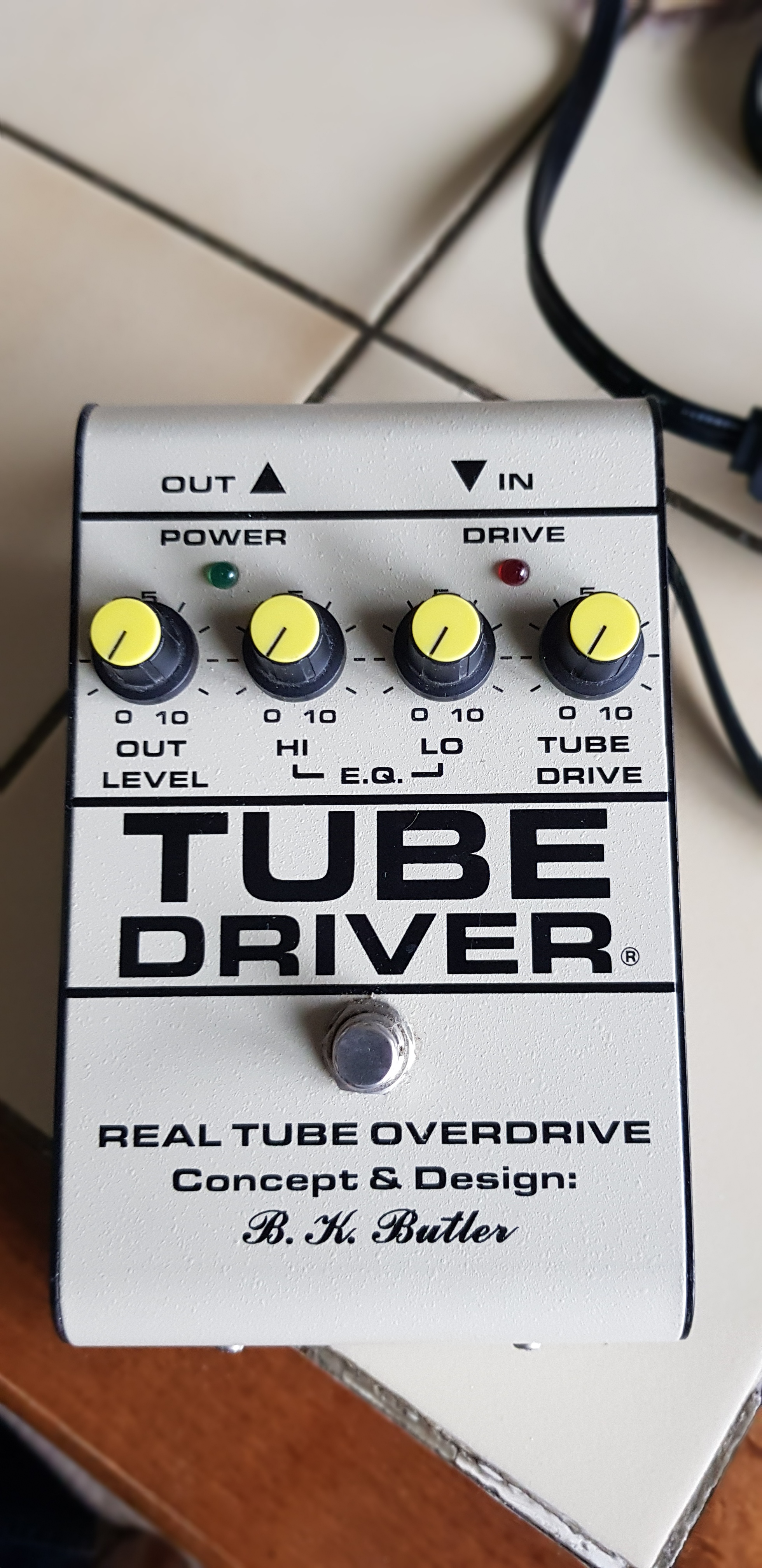
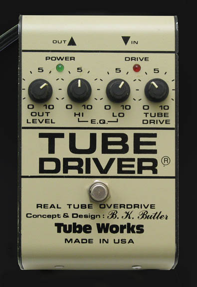
Princeton reverb fender layout schematic tube tremolo schem mod sf schematics circuit 1964 1973 amplifer stokes sfpr manual service 2nd 35W Tube Power Amplifier With El34 Circuit Diagram Schematic .orgĭynaco schematics st70 altec dynakit lansing diyaudioprojects williamson amplificateurs sunn solarus eletronica el34 scheda pinout audiocostruzioni amplificatore brom push eletricidade Wiring For SABS (South African Bureau Of Standards) 7 Pin Trailer Plug Wiring Diagram For 100015 Amp/V Meter – Drok.Blog drok Wiring Diagram: 42h wiring diagram Pin On Wiring Diagram in. Motorhome hooking The Unique Guitar Blog: The Fender Princeton Amplifer What Size Wire For 30 Amp Rv Service - 1500+ Trend Home Design - 1500 BK BUTLER REAL TUBE OVERDRIVE - The Tube Driver is a boosteroverdrive pedal with a simple ic and vacuum tube driven preamp circuit inside, used by musicians. This pedal does indeed include a real 12AX7 tube inside the enclosure. Butler Tube Driver tube driver butler bk wiring schematic chandler tubeworks diagram overdrive patent voltage low 120v Wiring Question ġ20v wiring question Wiring Diagram PDF: 12ax7 Heater Wiring Diagram įilament 12ax7 diyaudio Why Point To Point Wiring Is #1 With Tube Amps amps tube point wiring why came Housing Wiring Schematic image found in the (expired) U.S.

Chassis Wiring Conduit Installation Ģ330 conduit B.K. Kt88 williamson schematics el34 thegriftygroove diyaudio Guitar4geek: Building A Tube Amp Fender Champ 5f1 Model Copy ĥf1 diagram wiring fender champ amp tube schematic parts mod chassis mojotone 12AU7 / ECC82 Cathode Follower Tube Preamplifier Schematic | Audio 12au7 follower cathode schematic tube audio preamplifier amplifier circuit ecc82 vacuum schematics preamp amp diagram valve diyaudioprojects stage low guitar Pin On Tube-Amp 811a amplifier tube vacuum circuit circuits 10w valves gr diagram produced final audio amp tubes grid stereo electronics αποθηκεύτηκε από Figure 4-11. 35W Tube Power Amplifier With El34 Circuit Diagram Schematic .org 17 Pictures about 35W Tube Power Amplifier With El34 Circuit Diagram Schematic : 12AU7 / ECC82 Cathode Follower Tube Preamplifier Schematic | Audio, Pin on Tube-Amp and also 35W Tube Power Amplifier With El34 Circuit Diagram Schematic. Most players find a 'sweet spot' about 2:30 - 3 o'clock on the control. It does not change the EQ directly but because the way the tube responds can be varied you will hear EQ differences at various settings. I absolutely LOVE the BK Butler tube driver, it was and still is a staple in many famous guitar players distortion tone. I read I would need 30v DC and a voltage divider to feed the IC with, but I didn't understand well how much voltage I would need to feed the heaters with.35W Tube Power Amplifier With El34 Circuit Diagram Schematic. Technically it varies the electrical 'strength' of the tube and that affects gain, texture and dynamics. Bk butler tube works tube driver pedal 9 volt schematic driver.

My second question is about the possibility of DC powering, which I read in the thread I mentioned above. Bk butler tube works tube driver pedal 9 volt schematic. As it also differs from the other two in the power supply section, I'm wondering if the noise issues I read about in a previous thread ( ) may be due to some "lacks" in the older schematics.īasically I'm asking you which of the schematic I'd better follow.
BK BUTLER TUBE DRIVER SCHEMATIC SERIAL NUMBER
It says to be traced from a tube driver of which the original serial number and PCB number are given. On the contrary, the third schematic (which is very new) contains various differences with the first two, even if the basic layout is the same. I suppose John Greene's schematic is the one used by the majority of the ones who have already built this pedal. Predictability runs all through the plot.
BK BUTLER TUBE DRIVER SCHEMATIC UPGRADE
The only difference between the first two is the value of two caps in the tone stack (0.47u each in the GGG schematic, 0.047u each in John Greene's), which may be a typing error in one of the two (in any case, which value is correct?). Bk butler tube works tube driver schematic Gamecube controller adapter switch sold out Lightwright 6 upgrade The second half typically gets all the lead characters in one place and thus begins the chaos.

I found one at General Guitar Gadgets ( ), one from John Greene at and one at. I'm planning to build a Chandler Tube Driver and I found three schematics.


 0 kommentar(er)
